It’s been a while since I posted part 1 of my build, and things have been slowly progressing. Here I will show some of the disassembly process, and the basic mock up of the component placement.
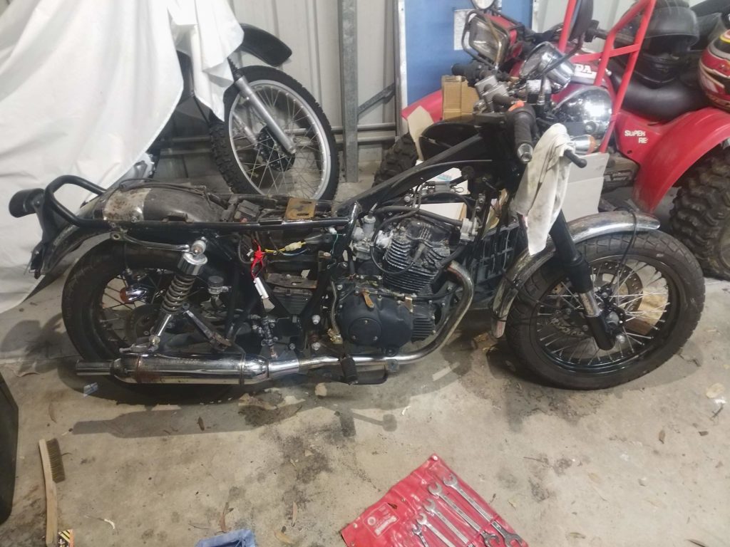
The fuel tank and seat are removed first.Then the exhaust, engine, gearbox, fuel and battery systems are removed
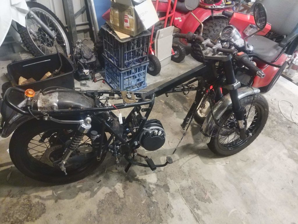
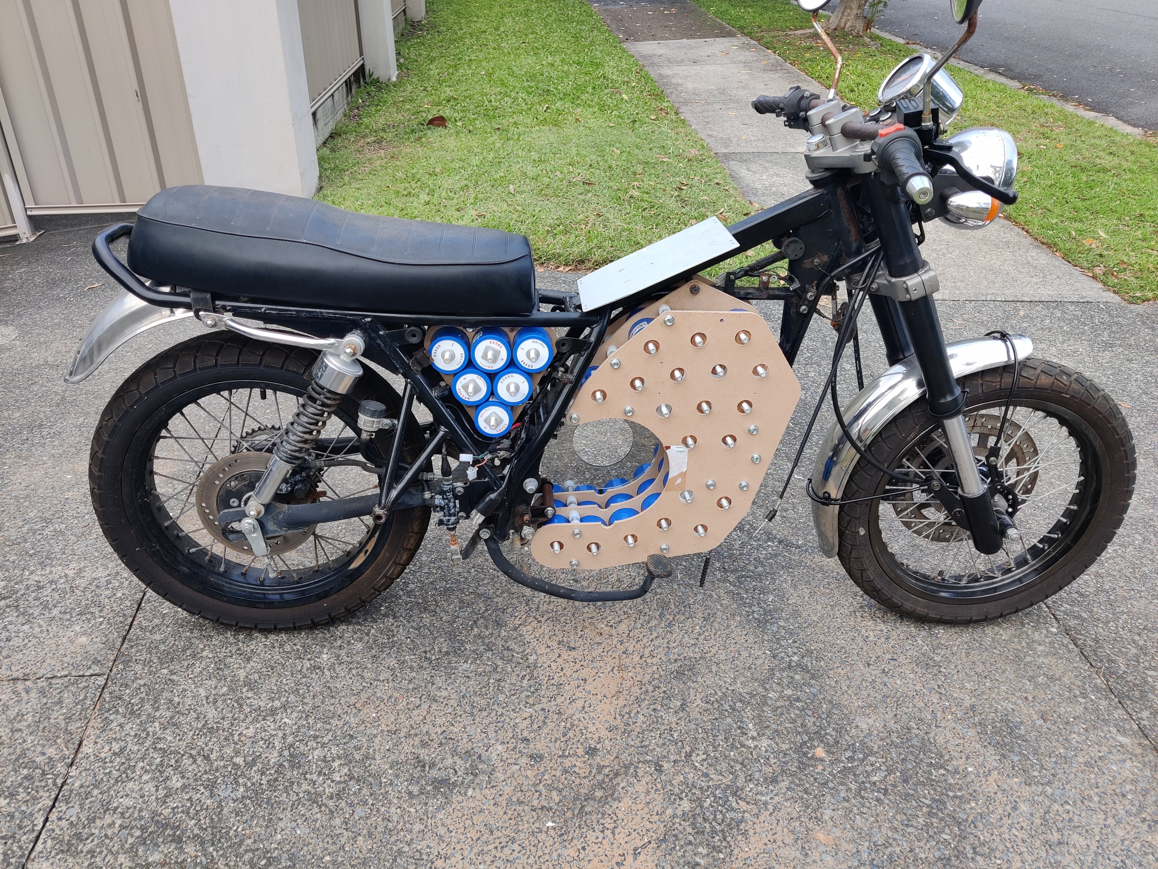
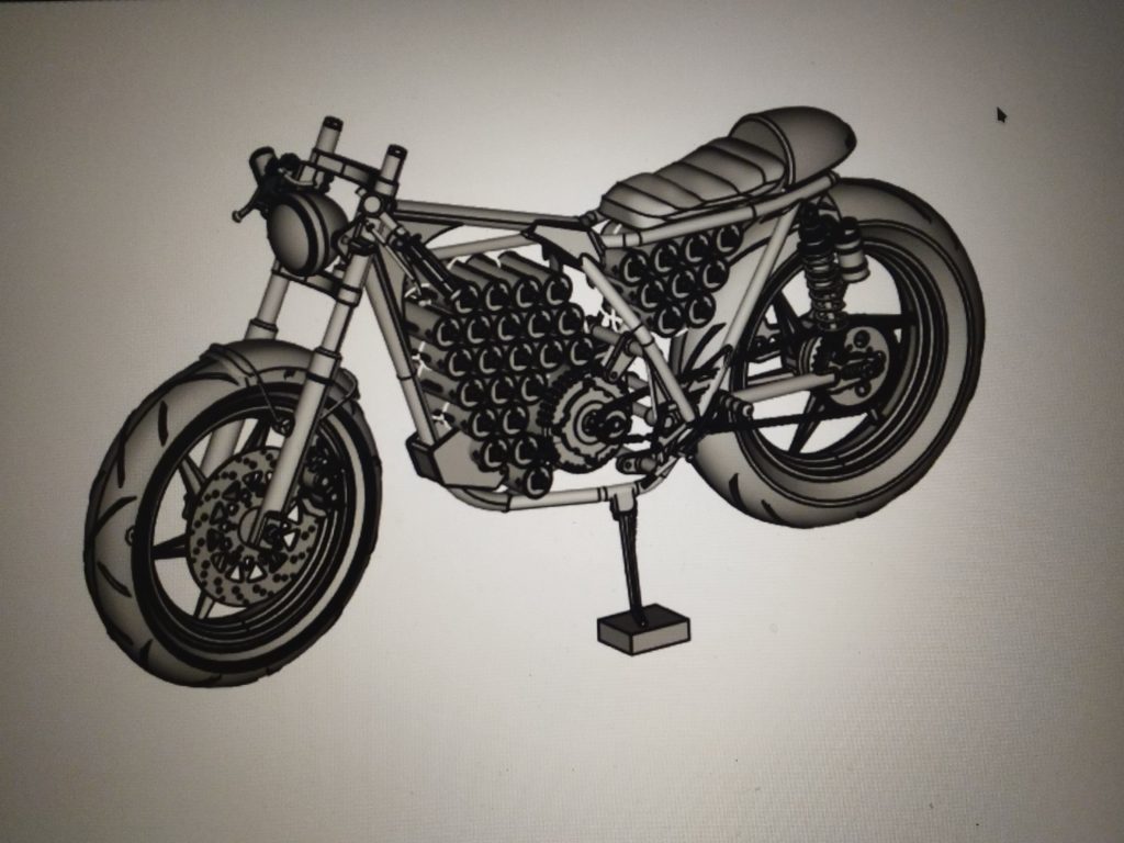
The fuel tank, seat, exhaust, engine, gearbox, fuel and battery systems were all stripped out of the frame. I then tried to mock the position of the motor to get an idea of how the engine mounts would work. I tried a few different designs which I initially cut out of plastic just to get the sizing right.
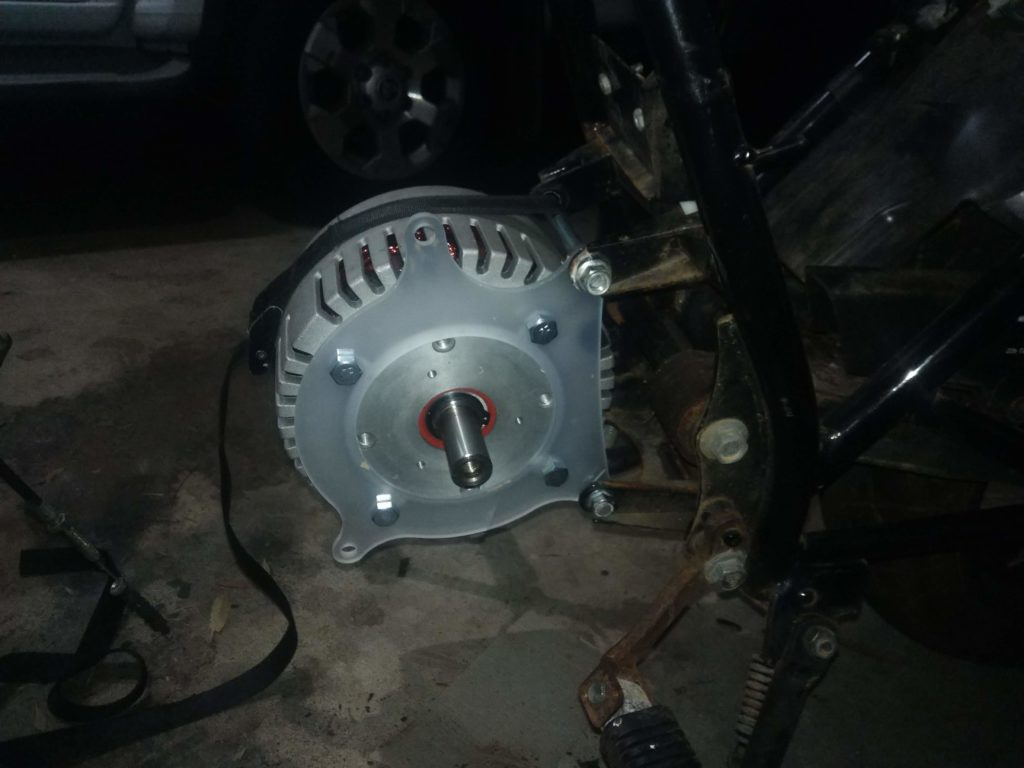
Attempt 1 – FAIL (too weak when mounted)Attempt 2 – FAIL! (The frame requires reinforcing)
The first two designs were unsuccessful. The first was far too flimsy when mounted, and the second did not correctly reinforce the frame of the motorcycle. By the third attempt, I had something that looked like it would work.
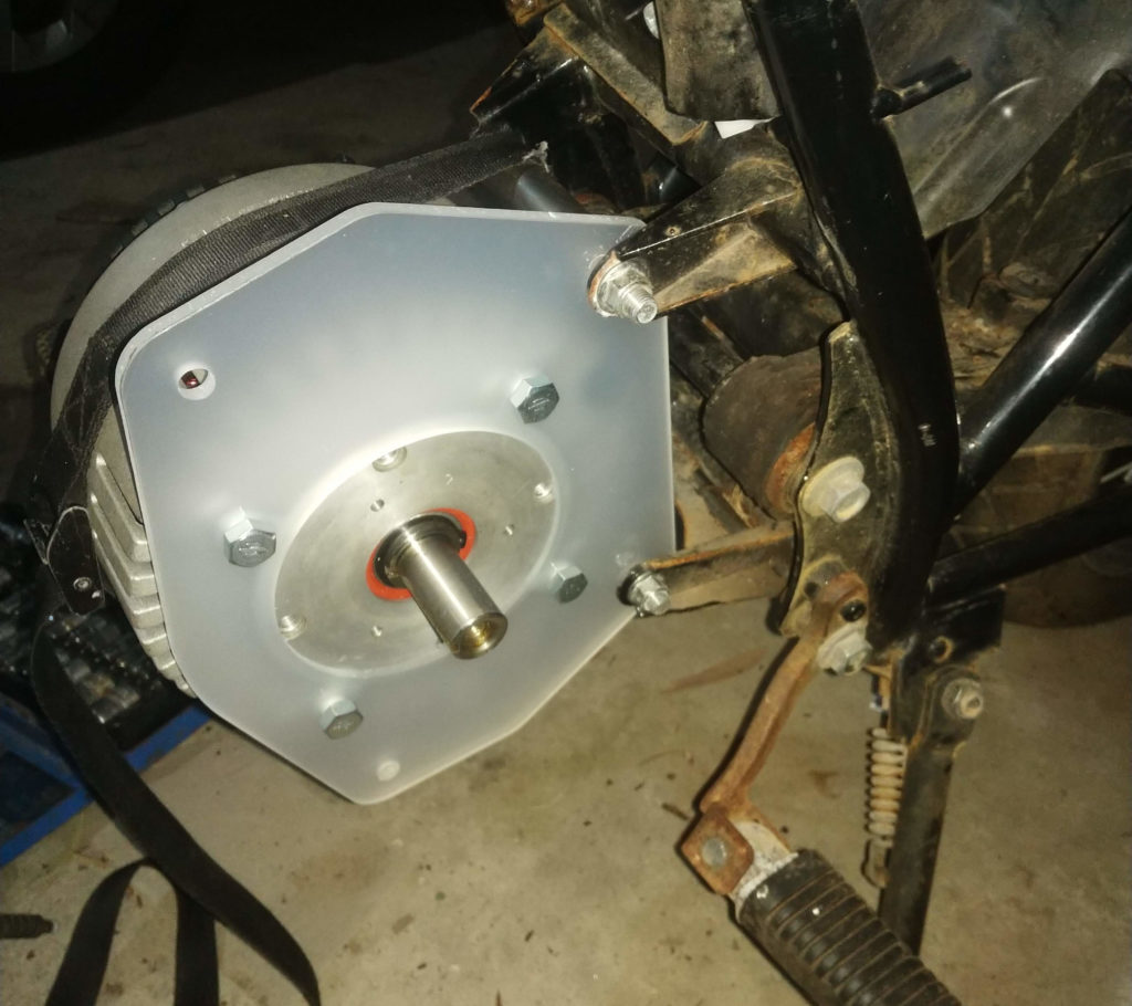
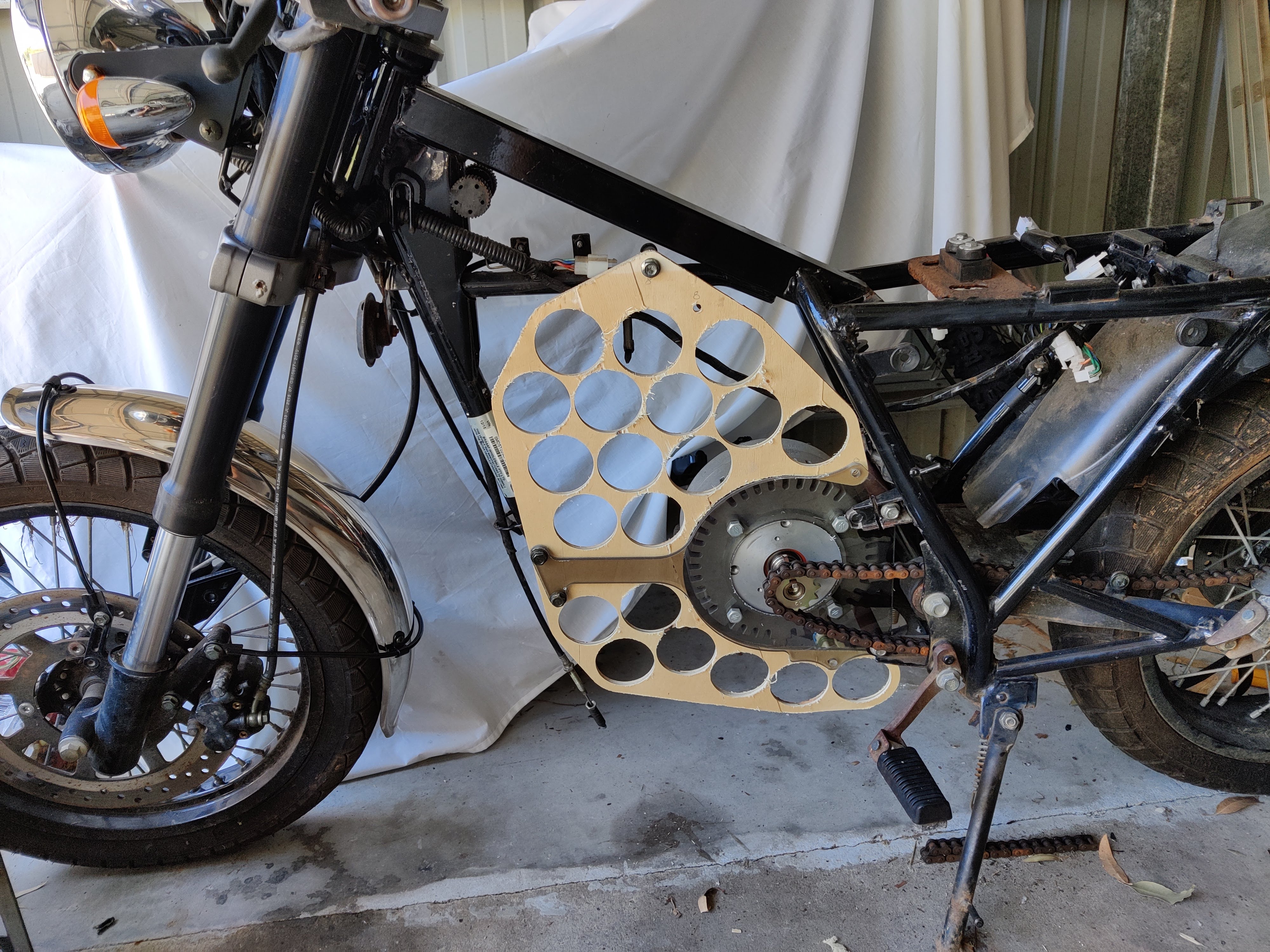
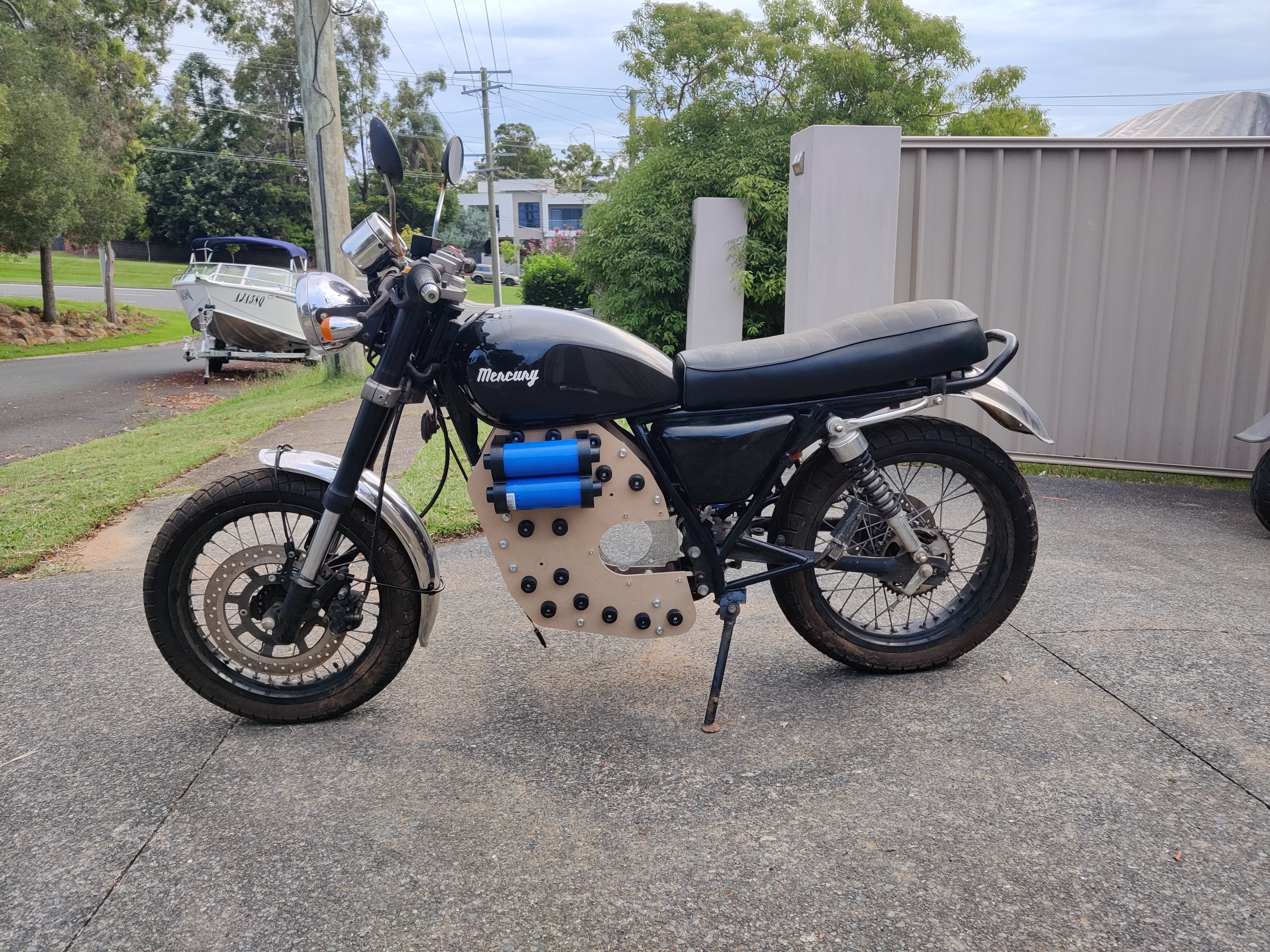
Attempt 3 – SUCCESS!
Initially I cut the components on my CNC machine in plastic and timber because they were much easier and cheaper to work with than the steel and polycarbonate materials from which the finished design will be constructed. These mock components allowed me to work out how everything would fit together, and were easy to re-make when I discovered issues with the construction.
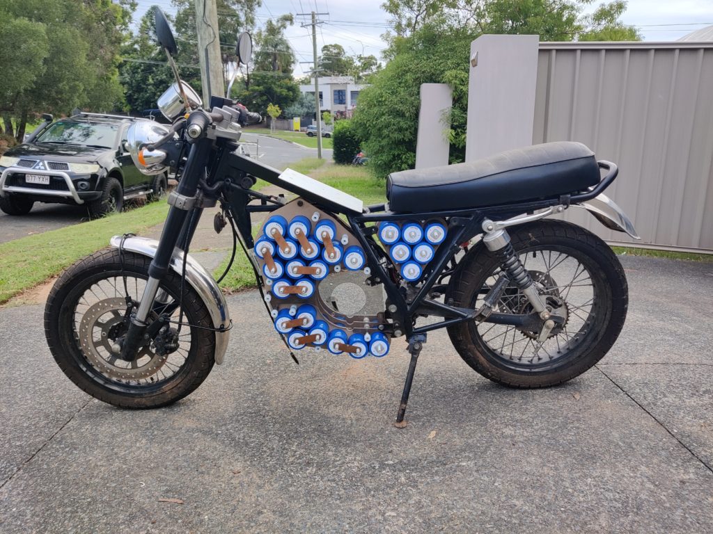
Now that I have the position of the major components mocked up I can start manufacturing the finished parts out of their final material. Stay tuned for part 3 where I start the final assembly.
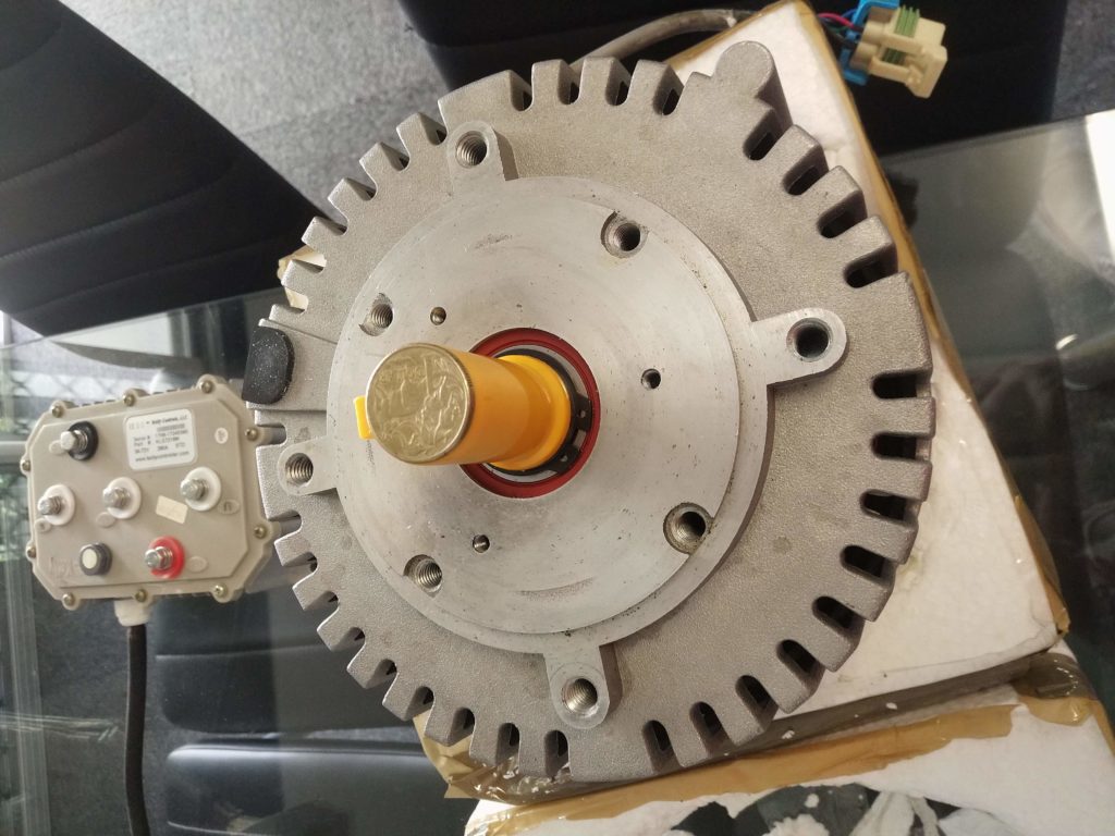
This is the first article of many about my latest project which is an electric motorcycle. It is a personal project that I thought may interest visitors to this site. I have wanted to start a full sized electric motorcycle build for a while, but components for these types of projects can be difficult to come by. I finally decided to pull the trigger on the project when I was able to buy a second hand, but unused motor and controller from a very helpful person who had it sitting around for a while (Thanks Robert!).
The motor is a Motenergy Electric LLC ME0201013001 ( an old version of Motenergy ME0907 without an internal temperature sensor ). It is a three phase brush-less permanent magnet motor, capable of running at 100 amps continuously, with a one minute rating of 220A. It is paired with an old version of the Kelly KLS7218M which is a 3 phase sine wave controller capable of 100 amps continuous, and 280 amps peak drive current. I am cautious of running these two components at their limit because it seems that some specifications for the newer version of the motor state an 80A/200A rating, and the newest version of the KLS7218 controller has an 80A/250A rating. I am not sure whether there were changes to the design, or whether experience showed that the specs needed de-rating.
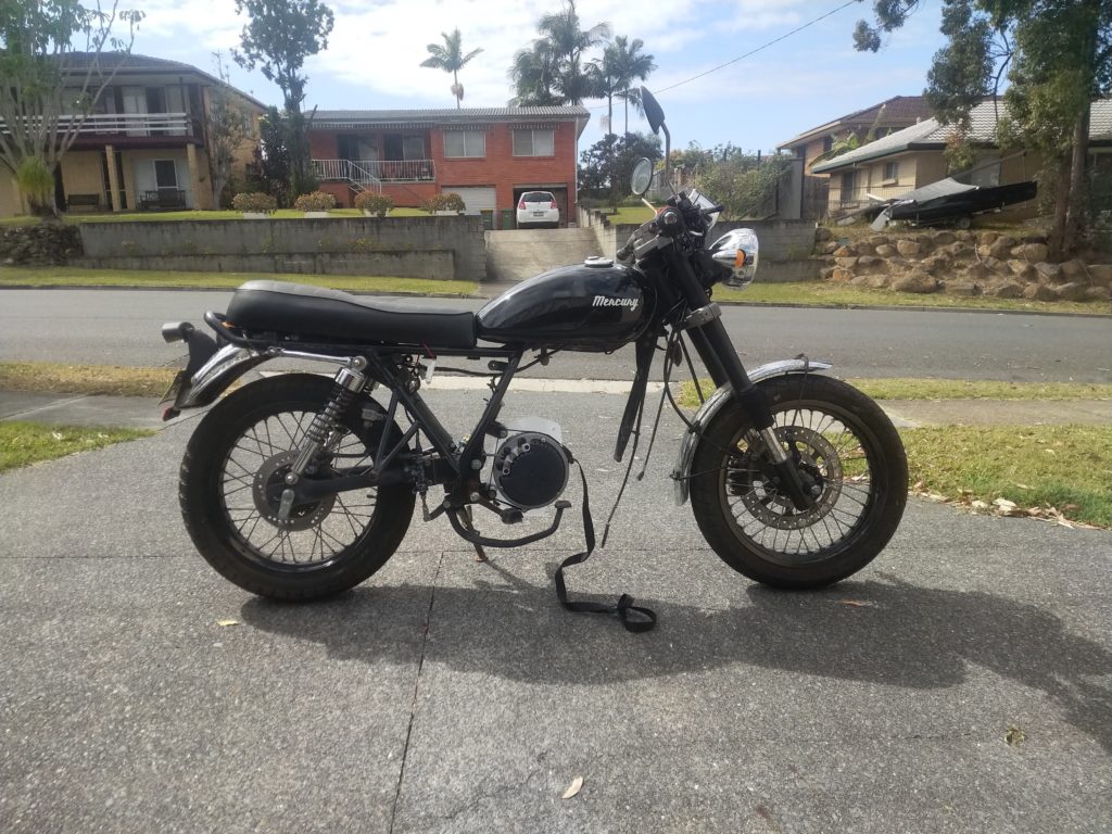
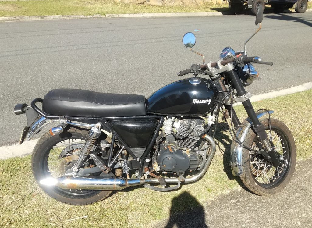
After getting hold of a motor and controller, I bought a donor bike to base the build on. It is a 2015 Braaap ST250 “Mercury”. Braaap (Sol Invictus) are an Australian company, but the bikes are made in China. Whilst it is a 250cc motorcycle, it is essentially the size of a 125cc commuter. The 14hp output of the petrol engine is only slightly more than what most 125cc Japanese motorcycle engines are capable of producing. This was a one of the factors in choosing the donor bike. I didn’t want the electric version to be any less powerful than the original bike. The small, light frame and large engine bay make for a good candidate. The bike was sold on Facebook as not running because the previous owner had abandoned it without leaving keys. It had been sitting outdoors for a couple of years, but only had 960kms on the clock so everything has very little wear. With a little hot-wiring expertise I managed to get it started. The motor was actually in pretty good condition and I felt a little bad about pulling the bike apart.
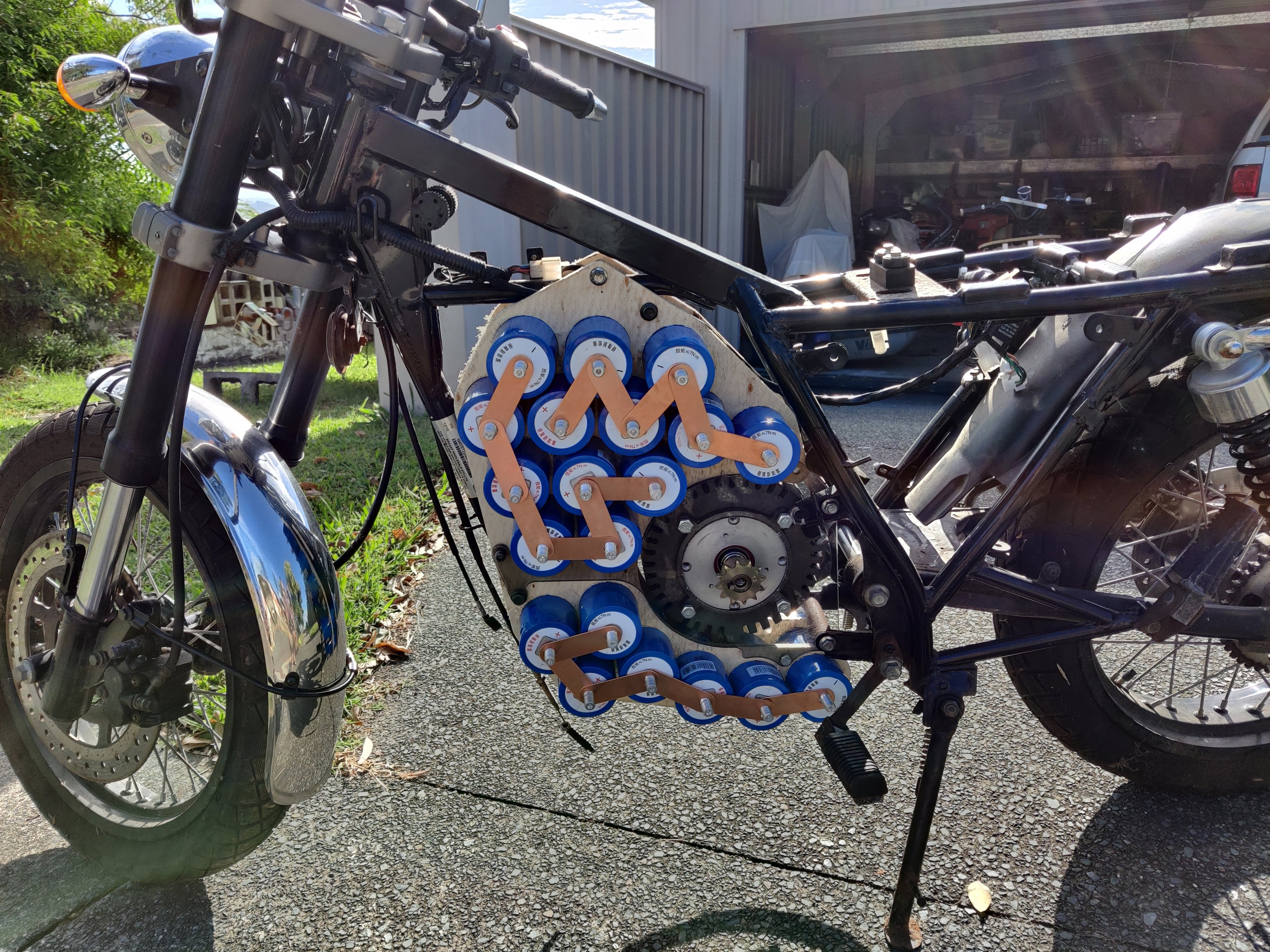
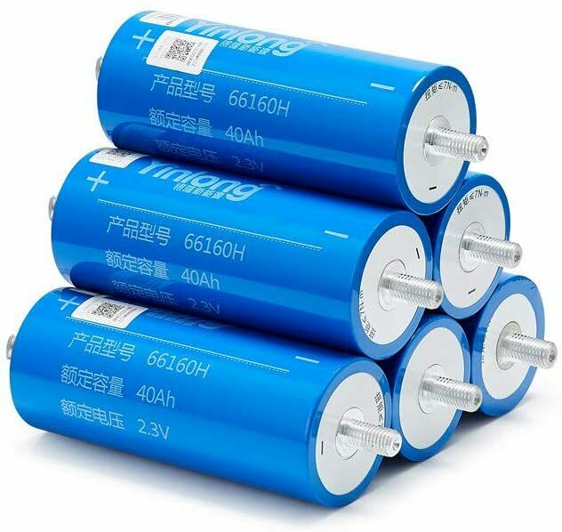
After doing some research on battery technology, I was concerned that the LFP (LiFePo4, or lithium ferrophosphate) batteries that would physically fit in the frame would not be capable of supporting the 220A of peak current draw that the electric motor would pull. Such a high discharge rate also has a degrading effect on most other lithium chemistries. After doing some research I stumbled across a fairly recent technology, LTO (Lithium Titanate). These batteries are interesting because they are capable of massive peak output (10C), have an extremely long cycle life (20,000 cycles or so), and have a very long shelf life (estimated at 20+ years). The down side is that they have a lower energy density than other batteries due to their lower cell voltage (2.3v as opposed to 3.2v for LFP and 3.7v for other lithium chemistries). So I placed an order for 32 40Ah cells to make a 72V/40Ah battery. As of writing this I am waiting for them to arrive on a slow boat from China (literally).
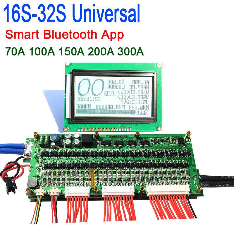
I also need BMS to balance and protect the cells, and I wanted a battery computer to calculate range and consumption. Although I generally like to build these interesting components myself, I found a BMS that also acts as a battery computer, with the added advantage of a bluetooth interface. After having built many multi-celled LFP scooters, one of the big issues that I found with high cell count batteries is finding what has caused a BMS to trip out. Generally it is a poor connection to one of the cells, a damaged BMS sense wire, or when the batteries get older, a failed cell. With no indication except a tripped discharge FET it can be difficult to trace the issue. This BMS has the added advantage of displaying cell voltage for every cell, as well as having a status indication so you know why you’re not going anywhere. It also has a documented serial protocol so that I could design my own display module, or perhaps reprogram the included display module (depending on the breed of micro-controller used).
That’s it for major components! Look out for Part 2 where I disassemble the donor bike.